PRODUCT FEATURES
Large Loading Capacity
- There are more teeth in continuous meshing
- There are two instantaneous lines of contact, so the length of contact line is longer
- Under the same specification, compact dimension can be designed under the same transmitted power and the same transmission ratio
High Transmission Efficiency
- Easily establishing lubrication oil film
- Smaller friction coefficient
- Smoother functioning
- Lower noisiness
- Longer service life
- Saving energy
Grindablity
- Worm tooth can be ground
- Tooth surface hardness is higher ( HRC≥55 )
- Tooth surface roughness is lower ( Ra≤0.8 )
- Tooth accuracy grade is higher
MAIN PRODUCTS & APPLICATION
- Standard series of double enveloping worm gearsets
- Center distance (inch): 0.8, 1.0, 1.5, 2.0, 2.5, 3.0, 3.5, 4.0, 5.0, 6.0, 7.0, 8.0, 10.0, 12.0, 15.0,18.0, 21.837, 24.0, 28.0
- Transmission ratio I=5~70
- Custom made double enveloping worm gearsets
- Minimum center distance: 20 mm / 0.8 inch
- Maximum center distance: 1200 mm / 48 inch
APPLICATION
- Robot joints
- UGV
- Power wheelchairs
- Elderly scooters
- Scooters for disabled people
- Electric windows and doors
- Medical instruments
- Booster pump used on cars
- Car pedals
- Wind turbine tower hoists
- Power tools for food machinery industry
- Radar antennas
- Screw-down mechabism
DESCRIPTION
Double enveloping worm gear set mounted with axes at a 90 degree angle. This type of gearing is also called Globoidal worm gearing, but the term double enveloping is more commonly used worldwide recently.
GEARX brand double enveloping worm gearsets are manufactured by unique method, compared with the normal cylindrical worm gearsets, the double enveloping worm gearsets has more teeth in meshing, and has one more group of lines of contact, so the total load is divided among more individual gear teeth, and the load is further divided where teeth support two lines of contact, this superior load distribution greatly increases load carrying capacity.
Under the same physical size, the double enveloping worm gearing can endure higher load about 1.5 to 3 times higher than the cylindrical ones. With the same transmission power, its center distance can be reduced up to 20 to 40%.
FORMING PRINCIPLE
Use a gear with specific tooth surface as the generating gear, rotate around its axis i2, and make an hourglass worm blank rotate around the other axis i1 ( i1 and i2 are spatially staggered vertically ). The generated worm is called enveloping hourglass worm. See figure 1.
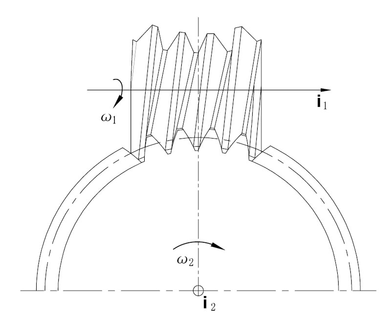
Figure 1 Enveloping forming of worm
The specific tooth surface can be plane, involute surface or conical surface, and the corresponding generated hourglass worm is respectively called planar enveloping hourglass worm, involute enveloping hourglass worm and conical enveloping hourglass worm.
These gears of specific tooth surfaces and their respective enveloping hourglass worms can form a gear pair, called the primary enveloping hourglass worm drive, also be simply called primary enveloping worm gearing. See figure 2.
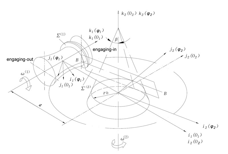
Figure 2 Forming of planar enveloping worm
The forming process of using a gear of specific tooth surface as the generating gear for enveloping to generate an enveloping hourglass worm is called primary enveloping.
The process of using this enveloping hourglass worm as the generating gear to generate another worm gear is called secondary enveloping. The enveloping hourglass worm and the worm gear generated by it form a gear pair called double enveloping hourglass worm gearing, also be simply called double enveloping worm gearing.
The planar double enveloping worm gearing has one more group of lines of contact when compared with the primary enveloping worm gearing. The distribution of these lines of contact can facilitate the formation of lubricating oil film. The angle between a contact line and corresponding direction of relative movement is 90°. The tooth surfaces are of concave-convex structure for meshing. The figure 3 shows the cross-section shape of tooth surface when the double enveloping worm gearset is meshing. There are two instantaneous lines of contact, forming two oil wedges, i.e. oil wedgeⅠand oil wedge Ⅱ. The worm tooth surface slides into the its counterpart’s worm gear tooth surface along the υ direction, bringing lubricating oil into the cavity between these two tooth surfaces separated by two lines of contact, thus a tooth flank oil sump is formed. As a result, in the subsequent meshing, oil wedgeⅠand oil wedgeⅡcan be supplied with sufficient oil.
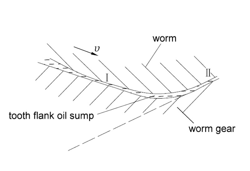
Figure 3 Tooth section of worm gear meshing
The excellent lubricating property between tooth surfaces allows the formation of good oil film even when this worm gear pair is operating at low velocity as long as the viscosity of lubricating oil is proper. The higher the relative rolling velocity is, the better the formation conditions for the hydrodynamic lubricating oil film will be.
The instanceous lines of contact are shown in the figure 4.
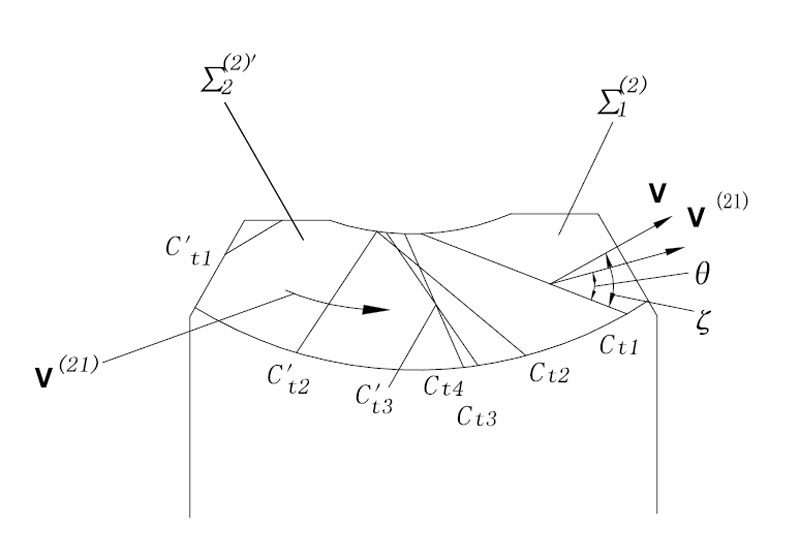
Figure 4 Lines of contact of the planar double enveloping worm gearing


