
Worm and Worm Gear
Lead
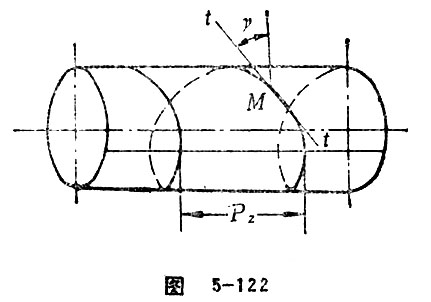
When a spiral line of rotational surface is intersecting with the same generatrix, then the distance between two arbitrary adjacent intersecting points is called lead. The lead of spiral line on the surface of cylinder is Pz=Pz=πmxz. This is a common term related to worm. See Figure 5-122.
Lead of Worm
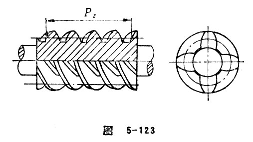
On an axial plane, the axial distance between worm and the same-side tooth profile of an adjacent gear tooth is called lead of worm. Lead of worm also refers to the distance measured by the movement of a tooth trace along the direction of axial line. The value is equal to the number gotten from the multiplication of axial pitch and head number, namely, Pz=Pxz=πmxz. The lead of cylindrical worm is shown in the Figure 5-113. See Figure 5-123.
Lead Angle
In the helical surface, the acute angle γ formed between the tangent of a point M getting through by a spiral line and the transverse plane of the helical surface of this point is called the lead angle of spiral line at the point M. Lead angle is a common term relating to worm. Generally speaking, lead angle of worm refers to the lead angle of spiral line at the speculated point on the reference surface. Cylindrical worm lead angles is: tgγ=mxz1/d1=z1/q=p/r※ (p is spiral parameter). Lead angle on a spiral line is complementary to that at the same location. See Figure 5-122.
Diametral Quotient
The quotient of the diameter of reference circle of worm divided by module is called diametral quotient. According to GB10085—88, diametral quotient is the second parameter (non-basic parameter) determined by module and the diameter of reference circle.
Worm Facewidth
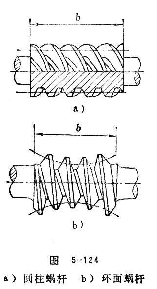
Worm facewidth refers to the length of toothed-part of worm measuring along the axial line direction on the reference surface. In general, cylindrical worm always takes: b1=(1.25+0.1z2)m. When adopting grinding gear, the Δb need to be added 20~45mm, namely, Δb=20~45mm, as the increasing of module. As for enveloping worm, , in this formula, z′, which refers to the tooth number that being enveloped. As for spiroid worm, b1=0.7a+mδ, and mδ refers to the module of the generatrix. See Figure 5-124.
Mid-plane
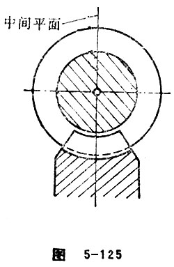
Mid-plane refers to the plane formed by the center-to-center line between the worm axis and worm pair. When the shaft angle , mid-plane also refers to the plane that includes worm axis which is vertical to worm wheel axis. Mid-plane is calculating plane for worm gear pair. The geometric size of worm, worm wheel can be calculated in this plane. See Figure 5-125.
Axial Plane of Worm
Axial plane of worm refers to the plane that includes worm axis. When , the vertical worm shaft includes the mid-plane of worm wheel shaft, which is one of the worm shaft planes. This plane is stipulated as the plane for calculating the size of worm and worm wheel.
Transverse Tooth Profile of Worm
The transversal cut by direction-vested plane on a worm helical plane is called transverse tooth profile of worm. The most commonly used terms relating to tooth profile are: transverse tooth profile of worm, axial tooth profile of worm, normal tooth profile of worm and base cylindrical tangent tooth profile of worm, etc.
Edge Contour Curve of Worm Turning Tool
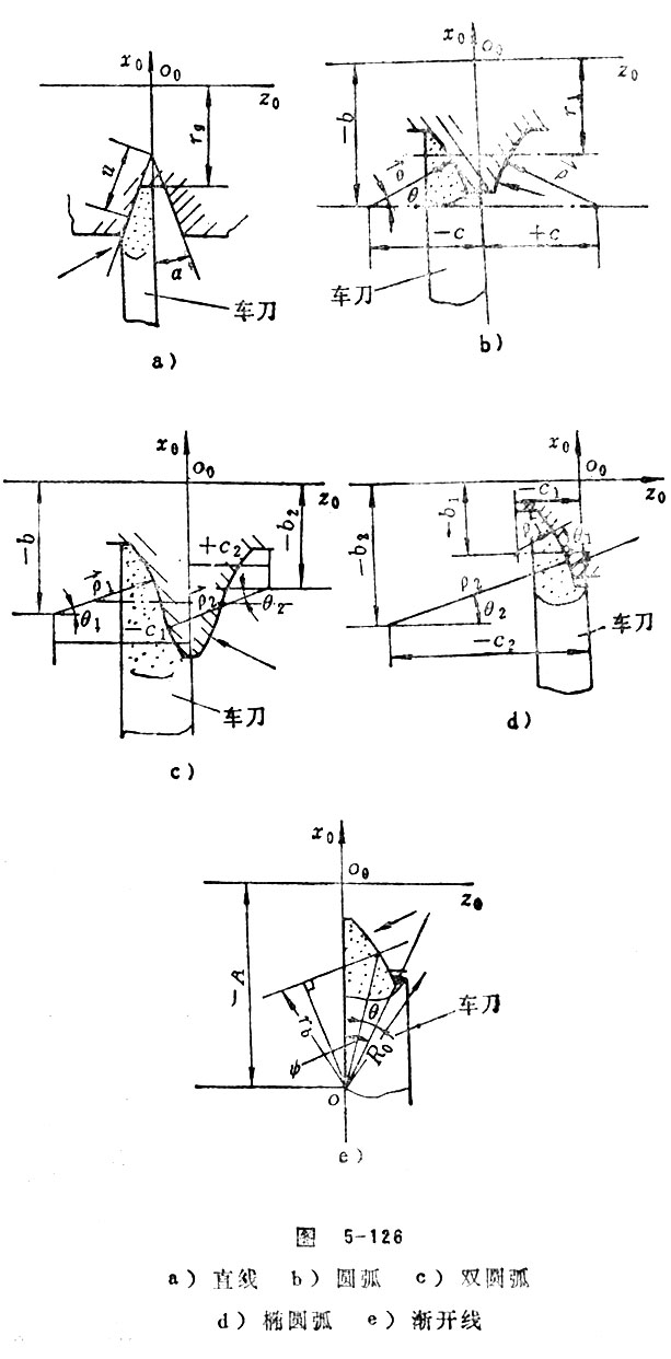
Edge contour curve of worm turning tool refers to edge contour curve of turning tool which forms local rotation axes cylindrical helical surface. Edge contour curve of worm turning tool is one of the main factors that determine the type of worm: the commonly used are: straight line, arc, double-arc, elliptical arc and involute, etc. (Figure 5-126)
Generating Rolling Line of Worm
A line on tooling that can form gear teeth flank according to its tooth shape, location and movement is called generating rolling line of worm. In fact, it is the edge contour of cutter. The commonly used generating rolling line includes: straight line, arc, and double-arc, elliptical arc and involute, etc.
Cutter Generating Line in Common Use of Worm
Cutter generating line is the generatrix that forms tooth flank of the first gear product. It is a basic geometric factor that determines the meshing character of gear pair and its operation quality. Considering the meshing character and performance of gear pair, the generally used generating line are straight line, inner arc, convex arc, biarc, elliptical arc, involute and cycloid, etc. (Figure 5-126)
Generating Angle of Worm
In a given plane, the acute angle formed between the transverse plane of worm and the tangent of given point on generating line of cutter is called generating angle of worm.
Generating Rolling Line of Worm Tooth Surface
A curve line section (including straight line), rolling across worm axis, forms a worm helix surface. This curve is called generating rolling line. The commonly seen generating rolling line of worm tooth surface includes straight line, arc, elliptical arc, biarc and involutes. (Figure 5-126)
Number of Threads, Number of Starts
The number of a worm spiral bur is called number of starts (number of threads). Currently, the number of starts of worm pair applied in China is commonly being z1=1~4. In order to improve the efficiency of worm-drive, people pay lots of attention to multi number of starts of worm.
Hands of Worm
See “right-hand teeth” and “left-hand teeth”.
Worm Wheel
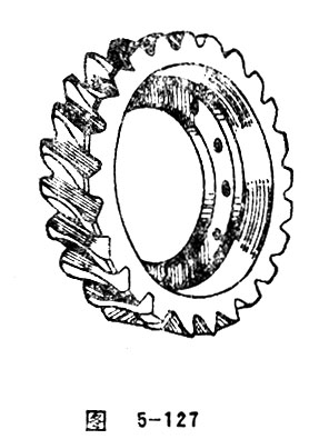
When a gear, as the bull wheel of alternating-axis gear pair, is meshed with its matched worm, the gear is called worm wheel. Worm wheel in general refers to helical gear of changed shape. Commonly, the reference surface of worm wheel is a toroid, but sometimes being cylinder or plane. Worm wheel ring of which the reference surface is toroid can be seen in Figure 5-127.
Mid Plane of Worm Wheel
Mid plane of worm wheel refers to the transverse plane of worm including line of centers. Mid plane of worm wheel is overlapped with the mid plane of worm gear pair.
Reference Toroid of Worm Wheel
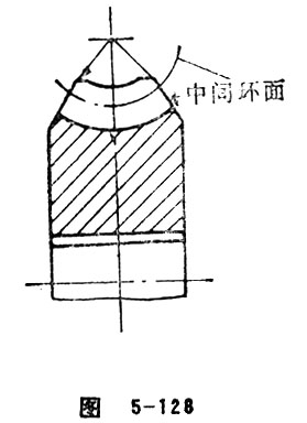
Reference toroid of worm wheel is a given imaginary toroid sharing the same shaft with worm wheel. Its tracing circle is the reference circle of worm matched with worm wheel in standard worm gear pair. The neutral circle radius is the center distance of worm gear pair and its mid plane is overlapped with that of worm gear pair. (Figure 5-128)
Tip Cylinder of Worm Wheel
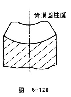
The tip surface of addendum surface of worm wheel, which is shown as cylinder or the shape of cylinder is called tip cylinder of worm wheel. (Figure 5-129)
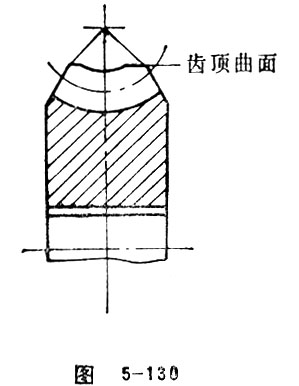
Tip Surface of Worm Wheel
Tip surface of worm wheel is located at the top gear teeth surface of worm. It is used to limit the radial size of the external cylinder and the tip toroid of worm wheel. Tip surface of worm wheel can be the combination of cylinder and torus, conical surface, plane and toroid etc. (Figure 5-130)
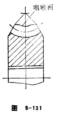
Gorge
On the tip surface of worm wheel, tip surface being toroid is called gorge. Taking the axis of worm wheel as axis, the toroid formed by gorge tracing circle is called gorge of worm wheel. See Figure 5-131.
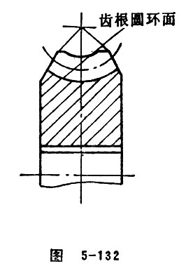
Root Toroid of Worm Wheel
Root toroid of worm wheel is an imaginary toroid that is consistent with the tooth bottom of worm wheel. (Figure 5-132)
Tip Circle of Worm Wheel
Tip circle of worm wheel refers to the intersecting line between tip cylinder of worm wheel and transverse plane. Tip circle of worm wheel is the largest circle of cylindrical worm wheel. (Figure 5-129)
Tip Diameter of Worm Wheel
Tip diameter of worm wheel refers to the diameter of the tip circle of worm wheel. (Figure 5-129)
Circle at Root of Gorge
Circle at root of gorge refers to the inner circle of tip toroid of worm wheel. When , circle at root of gorge also refers to the intersecting line formed between gorge (or addendum surface) and mid plane of worm gear pair. (Originally called tip circle of worm wheel) (Figure 5-133)
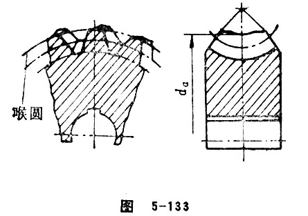
Diameter at Root of Gorge of Worm Wheel
The inner circle diameter of tip toroid of worm wheel(Figure 5-133) (originally called addendum circle diameter of worm wheel). The value is:
=
In this formula, x should use its own unit.
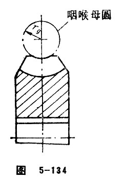
Generant Circle of Gorge
Generant circle of gorge refers to the tracing circle of tip toroid of worm wheel. (Figure 5-134).
Gorge Radius
Gorge radius here refers to the gorge radius of worm wheel. rg2=a-ra2=rf1+c*m. The gorge radius can hold a value that is relatively bigger than that of above mentioned as a way to improve the lubrication conditions. (Figure 5-134)
Reference Circle of Worm Wheel
Reference circle of worm wheel refers to the inner circle of reference toroid of worm wheel. It also refers to the intersecting line formed between the reference toroid circle of worm wheel and the mid plain of worm gear pair. Reference circle of worm wheel is the basic circle used to calculate the geometric size of worm wheel. The value is : .
Reference Diameter
Reference diameter here refers to the diameter of reference circle of worm wheel, it only bears relation with module and the number of teeth, namely, d=mz2. It bears no relation to the modification coefficient of worm wheel.
Root Circle of Worm Wheel
Root circle of worm wheel is the inner circle of root toroid of worm wheel. When , root circle of worm wheel refers to the intersecting line of root toroid and mid-plane of worm pair. (Figure 5-135)
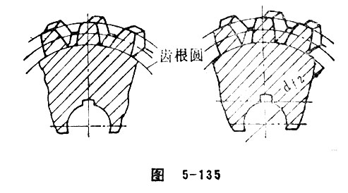
Root Diameter of Worm Wheel
Root diameter of worm wheel refers to the inner circle diameter of root toroid of worm wheel. The value is:
=
In this formula, x should use its own unit. See Figure 5-135.
Tooth Depth of Worm Wheel
Tooth depth of worm wheel refers to the radial distance between gorge circle (or tip circle) and root circle of worm wheel. The value is:
Addendum of Reference Circle of Worm Wheel
Addendum of reference circle of worm wheel refers to the radial distance between the gorge circle (or tip circle) and reference circle of worm wheel. The value is:
。
In this formula, x should contain its own unit.
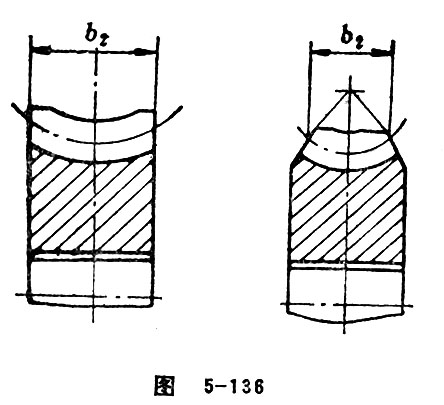
Face Width of Worm Wheel
Face width of worm wheel refers to the calculating width of teeth of worm wheel.
For cylindrical worm wheel, face width refers to the distance between the transverse line and the two intersecting point of tracing circle of reference toroid in axial plane of worm wheel shaft. (Figure 5-136) For conic worm wheel, face width of worm wheel refers to the length of gear tooth of worm wheel measuring along the generatrix direction.
Working Face Width of Worm Wheel
On the reference toroid of worm wheel, working face width of worm wheel refers to the distance of practical contacting area measured on its axis.
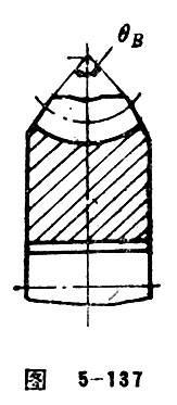
Width Angle
Width angle refers to the central angle pointed by the face width of worm wheel. See Figure 5-137.
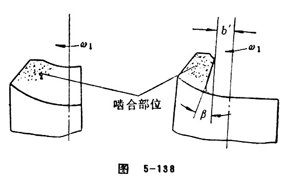
Sizing Worm Wheel with Half Tooth Width
For cylindrical worm gear pair, in the theoretical meshing area of worm wheel, the meshing can’t run properly and the meshing in central area is in the position of “glued dangerous area”. In order to avoid the meshing of these two areas and improve its capacity and transmission efficiency, sizing worm wheel with half tooth width is carried out as shown in the Figure 5-138. This kind of worm gear pair has good meshing characters. But it weakens the bending strength of worm wheel and only applicable in single operation.
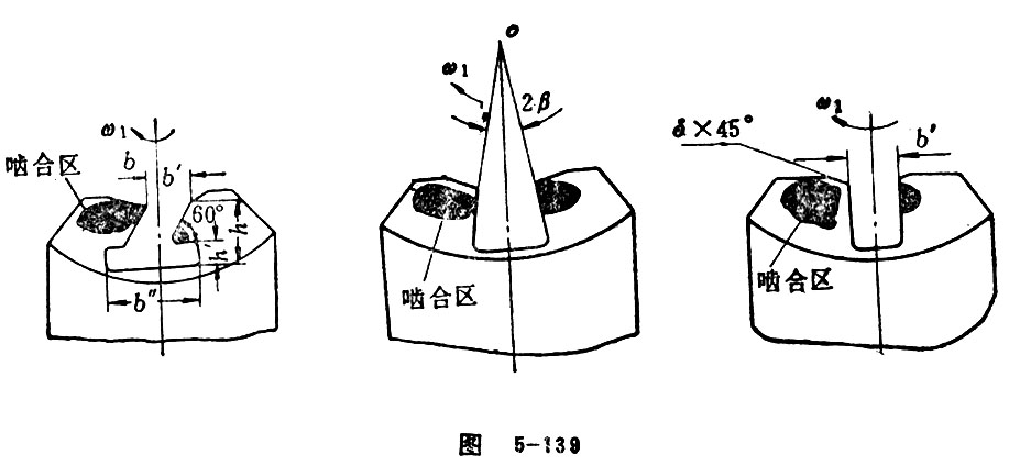
Sizing Worm Wheel
In order to avoid or decrease the meshing of dangerous area, sizing worm wheel is invented. This means to cut out the area that do harm to the formation of dynamic pressure oil-film as a way to realize its good meshing characters. This kind of worm wheel is called sizing worm wheel. Sizing worm wheel, matched with worm, is called sizing worm gear pair. The form of worm wheel is mainly shown in Figure 5-139.
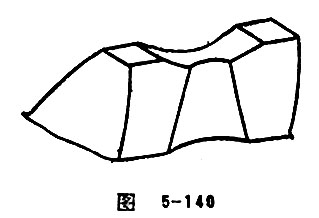
Dig Nest Worm Wheel
Putting the finger cutter in tooth space of worm wheel and cut the “dangerous area” in the tooth surface of worm wheel, the tooth surface is shown like nest-shaped vessel (Figure 5-140). Dig nest worm wheel and its matched worm can compose into dig nest worm gear pair. This kind of worm pair can form a meshing location with good performance and lubrication can be stored inside the vessel. After the cutting of “dangerous area”, the oil temperature can be decreased and the anti-glued capacity and driving efficiency can be improved.
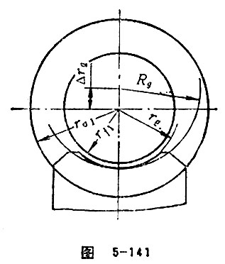
Increment of Gorge Radius
In order to realize “artificial oil protection”, and make the shape be wedge, the root surface of worm and the addendum toroid of worm wheel must be realized. Increasing the gorge circle radius is also a good measurement. Generally, , the increased gorge circle radius is Rg=rg※Δrg,Δrg=(0.5~0.9)m. Δrg is called the increment of gorge radius. See Figure 5-141.

 Hebei GEARX Limited