
Tooth Flank
The tooth surface between the tip surface and root surface is called tooth flank (see Figure 5-18). Tooth flank consists of three parts: the addendum flank, the dedendum flank and the blending surface.

Addendum Flank
Addendum flank refers to the tooth flank between the tip surface and reference surface (see Figure 5-18). Generally speaking, addendum flank is part of the active flank.
Dedendum Flank
Dedendum flank refers to the tooth flank between the reference surface and root surface (see Figure 5-18). Dedendum flank consists of blending root surface and part of usable flank.
Right Flank
Taking the transverse plane as the datum plane, the observer’s sight should be vertical to the transverse plane. Looking at a gear whose addendum being upward, then we can call the tooth flank on the right side the right flank. See Figure 5-18.
Left Flank
Taking the transverse plane as the datum plane, the observer’s sight should be vertical to transverse plane. Looking at a gear whose addendum being upward, then we can call the tooth flank on the left side the left flank. See Figure 5-18.
Fillet
Fillet refers to the tooth flank between usable flank and bottom land. See Figure 5-18.
Crest,Top Land
Crest refers to the tooth surface contained by the tip surface. It is located at the top of the gear. See Figure 5-18. Crest is non-working flank. For external gear, crest refers to the farthest tooth surface apart from the gear axis. For internal gear, crest refers to the nearest tooth surface apart from the gear axis.
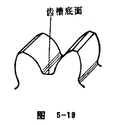
Bottom Land,Bottom of Tooth Space
Bottom land refers to the tooth space which is at the bottom of the tooth space, contained by the root surface and connecting with the blending root surface. See Figure 5-19. Bottom land is non-working tooth surface. In some cases, the bottom land may abrade into a simple line.
Usable Flank
Usable flank is enveloped with theoretical machine tool tooth flank. The meshing area on the working flank is called usable flank. The proportion of usable flank is only affected by the geometric shape of the active face of the tool and the corresponding installation sites of gear blank.
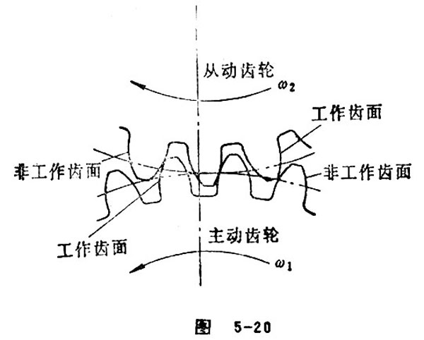
Non-working Flank
Non-working flank refers to the opposite tooth surface of the working flank. The non-working flank doesn’t participate in conjugate meshing when the gear pair is in operation. See Figure 5-20.
Working Flank
Working flank refers to the conjugate meshing surface joined by a pair of gear tooth when the gear pair is transmitting its movement and torque. See Figure 5-20.
Corresponding Flanks
Corresponding flanks refers the surfaces at the same side (all of the left or right) of a gear. See Figure 5-21.
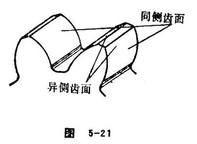
Opposite Flanks
In a gear, the right flank and the left flank are opposite flank of each other. See figure 5-21.
Coast Side
Coast side is a term used in vehicles when bevel gear is applied. As the vehicle moves backwards, the flank on which the bull gear (or pinion gear) and its matched gear contacting each other is called coast side. It also refers to the meshing flank of gear pair when the vehicle moving backwards.
Drive Side
Drive side is a term used in vehicles when bevel gear applied. As the vehicle moves forwards, the flank of bevel gear pair on which the bull gear (or pinion gear) and its matched gear contacting each other is called drive side. It also refers to the meshing flank of gear pair when the vehicle moving forwards.
Active Profile
In a pair of gear, the profile that can be meshed is called active profile. Active profile also refers to the profile formed between two tip surfaces of the meshed gears.
Active Flank
In the meshing process of gear pair, the flank that actually participates in conjugate meshing is called active flank. The size of active flank is not only affected by the shape of tooth flank, but also affected by the location and relative movement relation of the two matched gears. The maximum area of active flank is equal to the area of usable flank.
Conjugate Profile
The two mating flanks meeting the condition of ![]() are called conjugate profile.
are called conjugate profile.
Mating Flank
In a gear pair, the working flank that can mesh with each other is called mating flank.
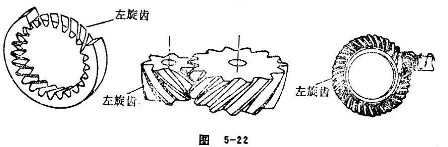
Left-hand Teeth
If taking the left spiral flank as gear teeth, we call the gear teeth the left-hand teeth. See Figure 5-22.
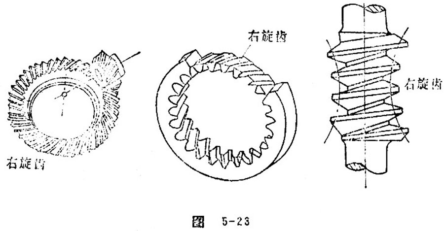
Right-hand Teeth
If taking the right spiral flank as gear teeth, we call the gear teeth the right-hand teeth. See Figure 5-23.

 Hebei GEARX Limited