
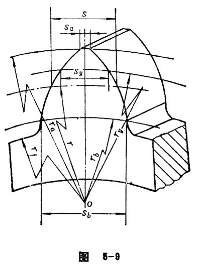
Transverse Tooth Thickness
In the end face of cylindrical gear, the arc length of reference circle between two sides of tooth profile is called transverse tooth thickness (see Figure 5-9). In terms of standard gear, the value is equal to the width of tooth space. According to GB1356-88, the transverse tooth thickness:![]() .As for the deflection gear:
.As for the deflection gear: ![]() . (“-”used in inner gear while “+”used in external gear)
. (“-”used in inner gear while “+”used in external gear)
Crest Width
In transverse plane of a gear, the arc length of addendum circle between two end surfaces of tooth profile is called crest width.
Transverse Base Thickness
In the end face of involute cylindrical gear, the arc length of base circle between the starting points of involute tooth profile on both sides of the gear teeth is called transverse base thickness. The formula is![]() . See Figure 5-9.
. See Figure 5-9.
Tooth Thickness at a Point
In the end face of a cylindrical gear, the arc length cut reversely from any arc of a circle is called tooth thickness at a point (see Figure 5-9). The value is![]() , in which the upper symbol of “
, in which the upper symbol of “![]() ” is applied in external gear while the lower symbol is used when it comes to internal gear.
” is applied in external gear while the lower symbol is used when it comes to internal gear.
Normal Tooth Thickness
As for helical-spur gear, herringbone cylindrical gear and cylindrical worm, the arc length of the normal spiral line of tooth trace between the two sides of the tooth surface is called normal tooth thickness (see Figure 5-10). The value is![]() .
.

Normal Base Thickness
In involute helical (or herringbone) cylindrical gear and involute cylindrical worm, the arc length of the two sides of base spiral line measuring along its normal spiral line is called normal base thickness. It is represented by![]() . See Figure 5-10.
. See Figure 5-10.
Normal Crest Width
In helical (or herringbone) cylindrical gear and cylindrical worm, the arc length of normal spiral line between the cylindrical spiral lines on both side of the tooth top. The value is sαn= sαt cosβ. See Figure 5-10.
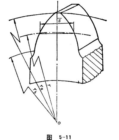
Transverse Chordal Tooth Thickness
In the end plane of the gear, the chord length corresponding to the indexing arc between the end tooth profiles of the gear tooth is called transverse chordal thickness. It is shown by ![]() (See Figure 5-11).
(See Figure 5-11).
Normal Chordal Tooth Thickness
The shortest distance between the two sides of tooth trace of gear teeth is called normal chordal tooth thickness. It is also equal to the chord length corresponding to normal tooth thickness.
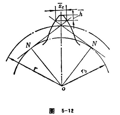
Constant Chord
When a tooth of an involute gear symmetrically contacts with two teeth of a basic rack, the shortest distance between the contacting lines distributing on the two sides of the tooth surface is called constant chord (see Figure 5-12). According to the tooth profile prescribed in GB1356-88, the constant chord is ![]()
=m(1.387-0.6428x).
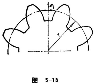
Tooth Space
Tooth space refers to the space between two adjacent teeth. The size of tooth space is often represented by the arc length of reference circle.
Transverse Space width
In the end plane of a gear, transverse space width refers to the arc length of reference circle between the two sides of the transverse tooth profile (see Figure 5-13). The value is et=pt-st.
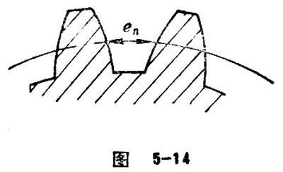
Normal Space width
In the tooth space of a helical or herringbone gear, the arc length of the normal spiral line between the two sides of the tooth trace is called normal space width (see Figure 5-13). It is represented by en.
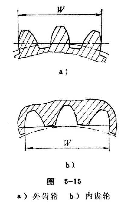
Base Tangent Length
For external gear, base tangent length refers to the base tangent distance (see Figure 5-15a) measured on the two outer sides of tooth surface of several adjacent teeth. As for internal gear, base tangent length refers to the base tangent distance measured on the two outer sides of tooth surface of several adjacent tooth spaces. In regard to involute spur gear, the base tangent length is calculated in the end plane. The formula is listed as![]() .
.
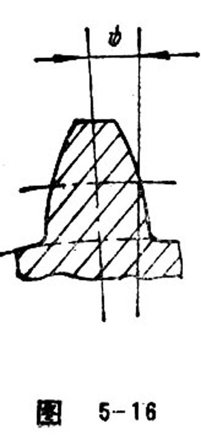
Tooth Thickness Half Angle
Tooth thickness half angle refers to half of the central angle corresponding to the transverse tooth thickness. It can be represented with ψ. See Figure 5-16.
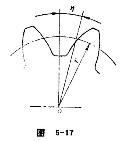
Space Width Half Angle
Space width half angle refers to half of the central angle corresponding to transverse tooth space. It is represented by η (see Figure 5-17).

 Hebei GEARX Limited